lcd_commander Entity Reference
Commander for LCD. More...
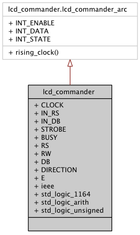
Architectures | |
| lcd_commander_arc | Architecture |
Libraries | |
| ieee | |
| standard IEEE library | |
Packages | |
| std_logic_1164 | |
| std_logic definitions, see file | |
| std_logic_arith | |
| arithmetic operations on std_logic datatypes, see file | |
| std_logic_unsigned | |
| unsigned functions use ieee.std_logic_unsigned.all; operators for std_logic_vector type, see file | |
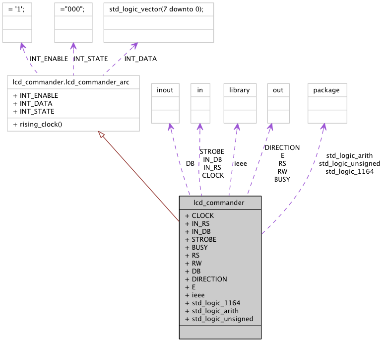
Ports | |
| CLOCK | in std_logic |
| input clock | |
| IN_RS | in std_logic |
| input status line for LCD | |
| IN_DB | in std_logic_vector ( 7 downto 0 ) |
| input data lines for LCD | |
| STROBE | in std_logic |
| the _|~|_ of length of two clock cycles that starts the writing to LCD | |
| BUSY | out std_logic |
| this line is 1 when LCD is busy | |
| RS | out std_logic |
| interface to LCD | |
| RW | out std_logic := ' 0 ' |
| interface to LCD | |
| DB | inout std_logic_vector ( 7 downto 0 ) |
| interface to LCD | |
| DIRECTION | out std_logic := ' 0 ' |
| interface to buffer in front of LCD (ML410 board specific); when 1 then data to LCD, when 0 data from LCD | |
| E | out std_logic := ' 1 ' |
| interface to LCD | |
Detailed Description
Commander for LCD.this entity sends command to LCD and waits until LCD is busy. this entity is the last stage before the LCD. It isues a command, asserts BUSY until LCD is done. STROBE should be only one clock cycle long
Definition at line 36 of file lcd_commander.vhd.
Member Data Documentation
BUSY out std_logic [Port] |
CLOCK in std_logic [Port] |
DB inout std_logic_vector ( 7 downto 0 ) [Port] |
DIRECTION out std_logic := ' 0 ' [Port] |
interface to buffer in front of LCD (ML410 board specific); when 1 then data to LCD, when 0 data from LCD
Definition at line 46 of file lcd_commander.vhd.
E out std_logic := ' 1 ' [Port] |
ieee library [Library] |
IN_DB in std_logic_vector ( 7 downto 0 ) [Port] |
IN_RS in std_logic [Port] |
RS out std_logic [Port] |
RW out std_logic := ' 0 ' [Port] |
std_logic_1164 package [Package] |
std_logic_arith package [Package] |
arithmetic operations on std_logic datatypes, see file
Definition at line 28 of file lcd_commander.vhd.
std_logic_unsigned package [Package] |
unsigned functions use ieee.std_logic_unsigned.all; operators for std_logic_vector type, see file
Definition at line 30 of file lcd_commander.vhd.
STROBE in std_logic [Port] |
the _|~|_ of length of two clock cycles that starts the writing to LCD
Definition at line 41 of file lcd_commander.vhd.
The documentation for this class was generated from the following file: